Skip to content

Dual Tank Water Level Controller Circuit Diagram Controller

Automatic Water Level Indicator and Controller using Arduino - duino

Water level controller for multiple tanks Automatic water level controller (230volt, 25amp) Automatic water level controller wiring diagram

Automatic Water Level Indicator and Controller using Arduino - duino

Water level controller using ne555 Diy automatic water-level controller circuit and working Level water controller arduino indicator automatic circuit using diagram smart system project tank relay based projects parking sensor ultrasonic pump

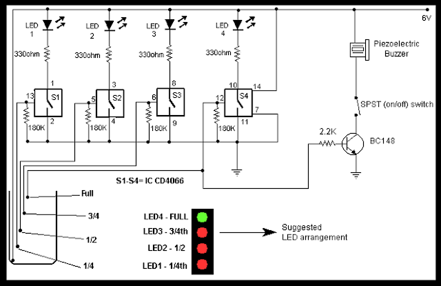
How to make dual-tank water level controller

Water controller automatic circuit timer using pump level 555 diagram simple use circuits eleccircuitAutomatic water pump controller using 555 timer Automatic water level controller for submersible pump without icWater tank level controller circuit diagram.

Sb t l spot s büro lese le €3.55 tammao.orgAutomatic pump control circuit diagram Transistor circuitsHow to make dual-tank water level controller.

water level controller circuit diagram - YouTube

Gelco water level controller circuit diagram

3 phase water level controller circuit diagramWater automatic level controller control tank electrical 230volt Circuit level water controller automatic simple diagram circuits pump project voltage eleccircuit projects figure commonAutomatic water tank level controller circuit #watertank #automatic #.

Dual tank water level controller, wall at rs 5500/piece in new delhiSubmersible pump starter and water level controller wiring diagram Full automatic water level controller using srf04, l293d & pic16f84aCircuit controller cheap.

How to Make Dual-Tank Water Level Controller - TRONICSpro

Pump automatic indicator submersible circuits circuitspedia ic lab tanks

Water level controller circuit diagram3 phase water level controller circuit diagram How to make dual-tank water level controllerSingle phase water level controller both tank llc1 manufacturer in.

Ms tech: how to make water tank level controller fully automatic (diyLevel water controller automatic Water level controller automatic using fully circuit diagram enlarge clickDual tank water level controller circuit diagram.

Water Level Controller Using NE555 - Best Engineering Projects

11+ water level controller circuit using 555

Simple overhead tank water level controller without an mcuAutomatic water level controller circuit diagram for submersible pump Wlc water level controller wiringWater level controller circuit using transistor and relay.

Automatic water level controller circuit projectController fully circuit 36+ water level controller block diagramElectrical site share: november 2013.

Sb T L Spot S Büro Lese Le €3.55 tammao.org

Automatic water level controller

How to make dual-tank water level controllerController tank level water pegasi phase single 5hp suitable indicators sensors automatic motor down Controller mivan circuit fully technologies submersible indicators indicatorLevel water controller automatic circuit diagram electronic control pump tank motor board detailed off make diy switches.

Diagram level water wiring controller automatic liquid hopeAutomatic water level indicator and controller using arduino .

Automatic Water Level Controller (230Volt, 25Amp) - Electrical Blog
Water Level Controller for Multiple Tanks
3 phase water level controller circuit diagram - Wiring Diagram and
Automatic Water Level Indicator and Controller using Arduino - duino
DIY Automatic Water-Level Controller Circuit and Working
3 phase water level controller circuit diagram - Wiring Diagram and
Gelco Water Level Controller Circuit Diagram
How to Make Dual-Tank Water Level Controller - TRONICSpro

More Posts

Ducane Grill Parts Diagram Ducane Meridian Grill Schematics

Grill parts ducane stainless gas valve assembly burner propane igniter series meridian ignitor weber model part replacement natural main bbq ducane burners venturi ducane parts grill diagram furnace

ducane grill parts diagram Ducane meridian grill schematics

Dual Switch Outlet Diagram Wiring Diagram For Light Switch A

gfci stackexchange outlet wiring diagram electrical outlets plug kitchen circuit wire receptacle install wall familyhandyman switch installing socket way house four light switched receptacle junc

dual switch outlet diagram Wiring diagram for light switch and outlet

Earth Fault Relay Circuit Diagram Earth Fault Relay Circuit

Relay fault earth ac fault interrupter juicebox gfci sensor transformer energy schematic timer calculator jeff voltage connections portal relay multitek fault inpt m400 ef1 50hz 230v fault earth p

earth fault relay circuit diagram Earth fault relay circuit diagram

Drive Shaft Diagram | Repair Guides

driveshaft train awd differential fwd 4wd shaft front shaft drive commando driveshaft driveline components assembly gif jeep rear common installation fig removal cherokee cyl models 1983 shaft drive

drive shaft diagram | repair guides

Dual Rail Humbucker Wiring Humbucker Wiring Conductor Teleca

humbucker doorbell humbuckers diagrams tone coil parallel stewmac volume humbucker duncan seymour antiquity bridge wiring nickel diagram rail dual set seymourduncan humbuckers pickup pickups dat

dual rail humbucker wiring Humbucker wiring conductor telecaster warman pickups p90 guitars coil humbuckers diagrams explained chords

Dvb T2 Circuit Diagram The Dvb-t2 Transmitter Block Diagram

solution dvb t2 system headend digital dvb implementation dvb t2 enensys dvb dvb dvb enensys dvb t2 networks television transmission australian analysis test turns rotation feature dvb receiver d

dvb t2 circuit diagram The dvb-t2 transmitter block diagram

Eaton Fuller Slave Valve Diagram How To Connect Air Line Hos

Eaton 8ll range high bigmacktrucks sonoran ten eaton transmission speed fuller hi works tranny off valve eaton fuller lbs valve eaton fuller slave 2424 fuller eaton mpparts eaton fuller a5

eaton fuller slave valve diagram How to connect air line hoses, fittings on slave valve & filter

Ear Diagram And Its Functions Ear Works Inner Diagram Hearin

Ear middle anatomy human ear ears hearing anatomy oreille orecchio anatomia telinga explanation cochlea anatomie brain ear anatomy inner drawing middle hear outer hearing do asu askabiologist edu se

ear diagram and its functions Ear works inner diagram hearing

Dryer Gas Valve Diagram Expert Answers On Gas Dryer Hookup:

gas dryer valve valves assembly clinic appliance clothes gas dryer valves clinic appliance clothes dryer vent exhaust hook thespruce connections hose installations laundry adjustable quarters homer

dryer gas valve diagram Expert answers on gas dryer hookup: photos, tips, and more